
ob_start_detected
head_banner_pro

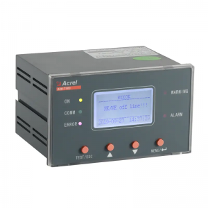
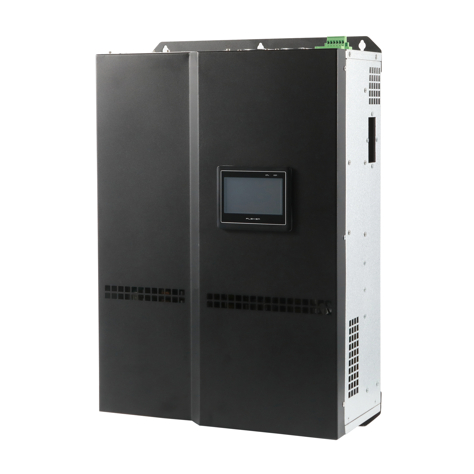
Acrel ANSVG Low-Voltage Static Var Generator

● Application Voltage: up to 380V
● Current Input: 1A/5A CT secondary input
● Protection: overcurrent, earth fault, current unbalance, short circuit
● Residual Current: 30–1000mA, optional with external RCT
● Communication: RS485, Modbus-RTU
● Relay Output: 2×SPDT
● Protection Class: Front IP54; Terminals IP20


Information

Parameter

Function

Download

ANSVG series · Static var generator

Compensate reactive power in under 5 milliseconds

ANSVG is a modular static var generator for low-voltage industrial and commercial networks. It reads the reactive demand and injects the exact compensating current — continuously, at 20 kHz, with no capacitor switching steps. Where a switched capacitor bank corrects one average value, ANSVG tracks the load cycle by cycle.

01

Overview

A static var generator is an electronic compensator. Instead of connecting capacitors in steps, the ANSVG module converts the measured reactive current into a switching pattern and injects a matching current back into the busbar. The result is continuous compensation: the power factor moves to the target value and stays there, regardless of where the load sits in its cycle.

The module is built around a DSP and FPGA controller driving an IGBT bridge through an LCL coupling reactor. Current transformers sample the line, the controller separates the reactive, harmonic and imbalance components, and the converter injects the correction. A closed loop re-measures the output continuously, so drift and load steps are corrected within the same cycle.

Because compensation is electronic rather than switched, ANSVG also corrects three-phase imbalance and can be set to generate or absorb reactive power within the module rating — the compensation range is adjustable from −1 to +1. It is supplied as a drawer module for cabinet assembly, as a wall-mounted unit, or as a complete wired cabinet.

Single module

Compensates a dedicated load group or one busbar section. Up to 12 modules can be paralleled on the same busbar and supervised from a single HMI.

Replacing capacitors

Suited to networks where the existing switched bank over- or under-corrects, where harmonic current would stress capacitors, or where a photovoltaic array keeps changing the active power flow.

At a glance
Power factor ≥ 0.99
Full response ≤ 5 ms
Instantaneous response ≤ 100 µs
Switching frequency 20 kHz
Module range, 400 V 30 – 150 kvar
Module range, 690 V 50 – 100 kvar
Parallel modules up to 12
Harmonic orders 5th – 13th

Values apply to the standard ANSVG module at rated conditions. Contact us for certified drawings.

01_ansvg-cabinet
02_ansvg-module
04_ansvg-cabinet-inside
03

Protection and control functions

The controller supervises the power stage, the network and itself. Protection functions fall into three groups: network conditions at the sampling point, converter health, and internal electrical limits. When a limit is reached the module restricts output to the rated current rather than tripping the supply — overload is managed by limiting, not by shutdown.

Monitored condition Alarm Action
Grid over-voltage and under-voltage Flagged and logged Output restricted
Missing phase or wrong phase sequence Flagged and logged Output blocked
Frequency out of range Flagged and logged Output blocked
IGBT bridge fault Flagged and logged Converter shut down
DC bus over-voltage and under-voltage Flagged and logged Output blocked
Module over-current Flagged and logged Current limited, then blocked
Module over-temperature Flagged and logged Output derated by airflow
Sustained overload Flagged and logged Automatically limited to rated current

The controller maintains more than twenty protective conditions in total; the eight above are the ones most often referenced during commissioning. Events are time-stamped and stored, up to 500 records.

Overload is handled by limiting, not by tripping.

When demand exceeds the module rating the output is held at rated current and the event is logged. The load keeps running; the shortfall stays on the supply until the demand falls back.

Sampling reference

The sampling CT defines what the module regulates. It can be placed on the load side or on the grid side, and the ratio is set between 100:5 and 10000:5.

When two CT sets are used, the grid CT and the module CT have to be connected in reverse parallel. Reversed polarity produces incorrect regulation.

05_how-it-works

Specifications

Technical Parameter Qualification
Accessory Power Supply Voltage Range AC/DC 85–265V
Power Dissipation —
Input Current Specifications ABCN (4-channel): 1A/5A 10%Ie–1000%Ie, ±2%
Residual Current Specification 30mA–1000mA ±2%
Frequency 45Hz–65Hz ±0.2Hz
Output Output Method Dual-channel Single-pole Double-throw Switch
Output Capacity Resistive Load; AC 250V 5A / DC 30V 5A
Installation and Usage Environment Workplace Scenario No direct exposure to rain or snow; no corrosive gases; no severe vibration
Relative Humidity ≤95% RH, No Condensation
Working Temperature -20℃ to +70℃
Storage Temperature -40℃ to +70℃
Altitude ≤2000m
Installation / Protection Level Embedded Installation: 88 × 88mm Panel: IP54; Terminals: IP20
Security Classification EMC Level III

Functions

Function Standard Configuration Optional
Measurement Function Three-phase Alternating Current √
Neutral Conductor Current √
Residual Current √
Protective Function Inverse-time Overcurrent Protection √
Inverse-time Grounding √
Three-stage Time-delayed Overcurrent Protection √
Three-stage Time-delayed Ground Fault Protection √
Current Imbalance √
Leakage Current √
Communication Function Modbus-RTU √
Digital Output Function 2 Single-pole Double-throw Switches √
Record Function 20 Fault Records √
20 Event Records
Display Function Liquid-crystal Display √
Setpoint Setting Function Operation Panel Modification √
Communication Amendment

Need the user manual, a wiring diagram or a quotation for your project? Ask us — we reply within one working day.

06_formats-and-dimensions
07_cabinet-clearances

  • Previous:
  • Next:

  • Technical Parameter Qualification
    Accessory Power Supply Voltage Range AC/DC 85–265V
    Power Dissipation —
    Input Current Specifications ABCN (4-channel): 1A/5A 10%Ie–1000%Ie, ±2%
    Residual Current Specification 30mA–1000mA ±2%
    Frequency 45Hz–65Hz ±0.2Hz
    Output Output Method Dual-channel Single-pole Double-throw Switch
    Output Capacity Resistive Load; AC 250V 5A / DC 30V 5A
    Installation and Usage Environment Workplace Scenario No direct exposure to rain or snow; no corrosive gases; no severe vibration
    Relative Humidity ≤95% RH, No Condensation
    Working Temperature -20℃ to +70℃
    Storage Temperature -40℃ to +70℃
    Altitude ≤2000m
    Installation / Protection Level Embedded Installation: 88 × 88mm Panel: IP54; Terminals: IP20
    Security Classification EMC Level III
    Function Standard Configuration Optional
    Measurement Function Three-phase Alternating Current √
    Neutral Conductor Current √
    Residual Current √
    Protective Function Inverse-time Overcurrent Protection √
    Inverse-time Grounding √
    Three-stage Time-delayed Overcurrent Protection √
    Three-stage Time-delayed Ground Fault Protection √
    Current Imbalance √
    Leakage Current √
    Communication Function Modbus-RTU √
    Digital Output Function 2 Single-pole Double-throw Switches √
    Record Function 20 Fault Records √
    20 Event Records
    Display Function Liquid-crystal Display √
    Setpoint Setting Function Operation Panel Modification √
    Communication Amendment
  • Write your message here and send it to us
    -->