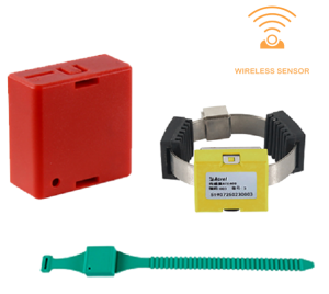

APD series Partial Discharge Detector
Product Introduction
At this stage, metal-enclosed switchgear is widely used in the power system, so the stability and reliability of the switchgear operation is the top priority.
The APD series medium-voltage switchgear partial discharge detector device detects the partial discharge signal of the electrical equipment during operation through ultra-high frequency sensors (UHF), ground wave sensors (TEV) and ultrasonic sensors (AE), so as to judge whether there are hidden insulation hazards inside the high-voltage electrical equipment, give early warning, and ensure the safe and reliable operation of the power system.
Temperature Display
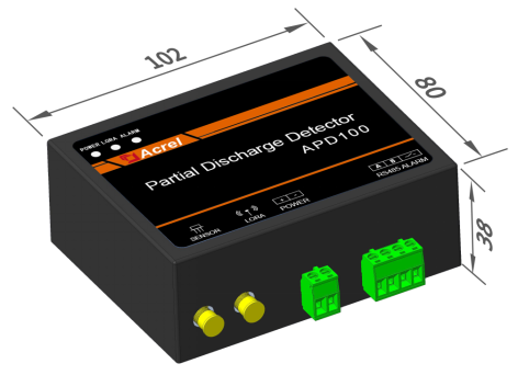
APD100 Series
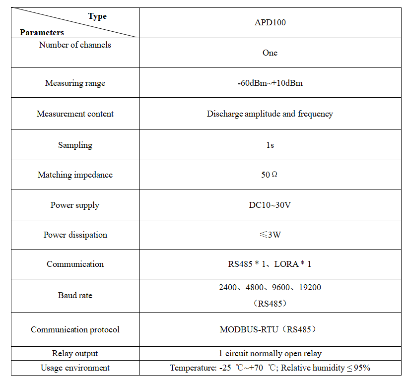
The APD100 UHF partial discharge detector adopts a guide rail (DIN35mm) installation method and can be installed in the secondary instrument room of the switchgear;which can be connected to DC10~30V voltage; The communication interface includes RS485 communication port and LORA wireless (wireless communication needs to be used in conjunction with our wireless transceiver ATC600-C)
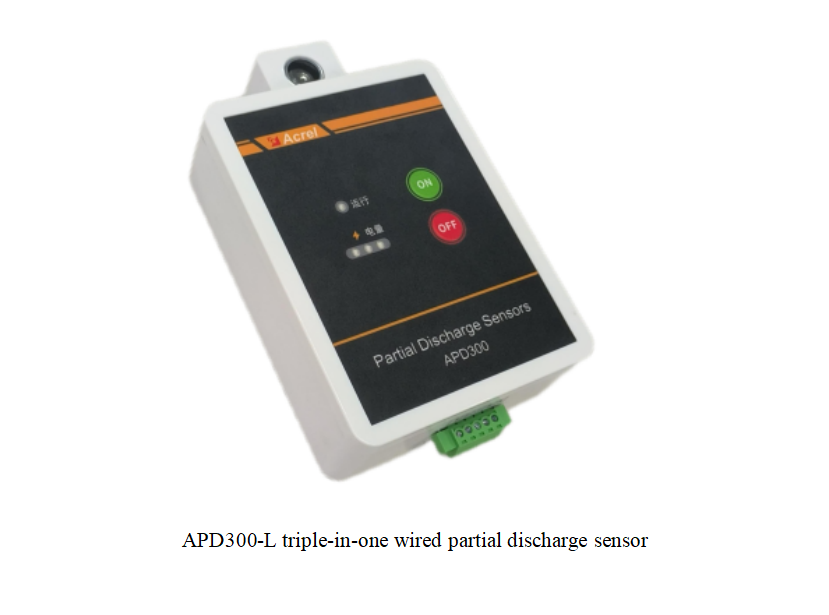
APD300-L Series
APD300-L triple-in-one wired partial discharge sensor adopts a strong magnetic adsorption mounting method and is installed on the cabinet wall in the cable compartment of the switchgear.
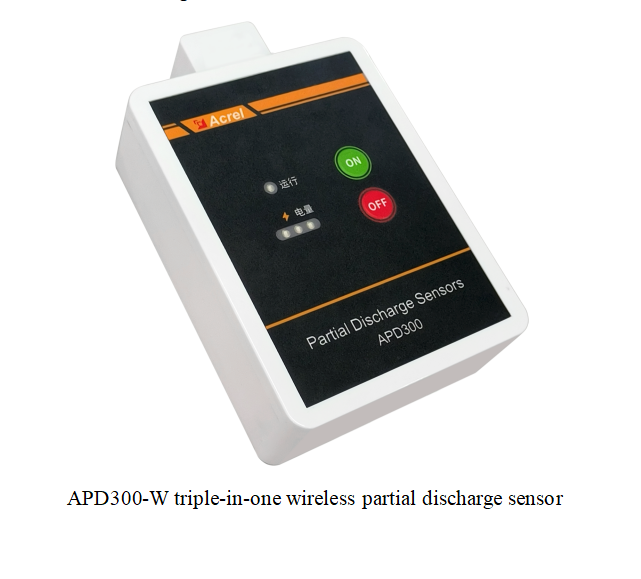
APD300-W Series
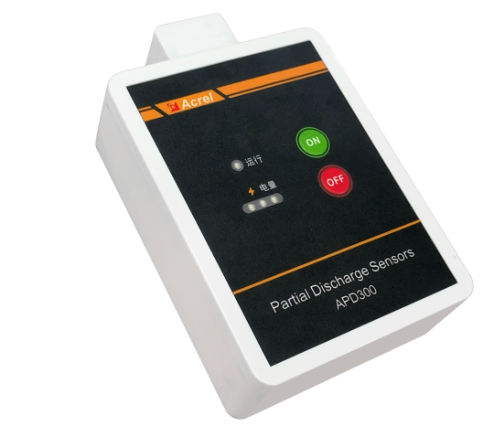
The APD300-L triple-in-one wireless partial discharge sensor indicator is shown below, "ON" is the battery on button, "OFF" is the battery off button, and has a running indicator and a battery indicator. LoRa transmits data wirelessly, without any peripheral connection interface (wireless communication needs to be used with our wireless transceiver ATC600-PD).
ATC600 Series
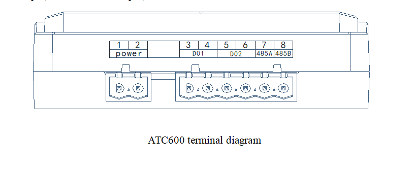
Wireless temperature measurement transceiver ATC600 terminal block. 1, 2 are power terminals, 3, 4 are DO1 output, 5, 6 are DO2 output, 7, 8 is A and B terminal of RS485 interface.
Need the user manual, a wiring diagram or a quotation for your project? Ask us — we reply within one working day.