
ADW600 Multi-circuit Wireless Energy Meter
General
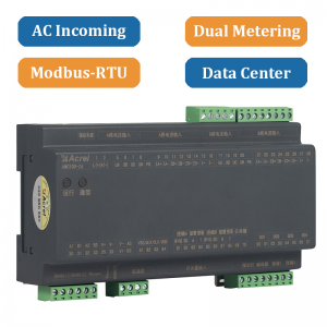
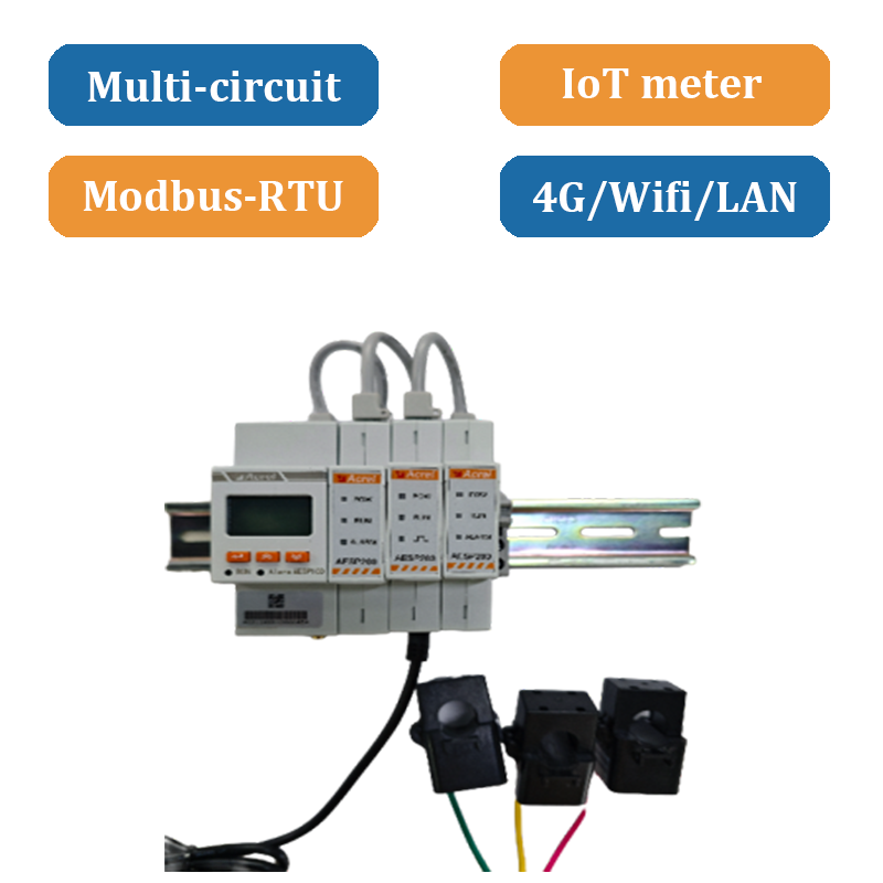
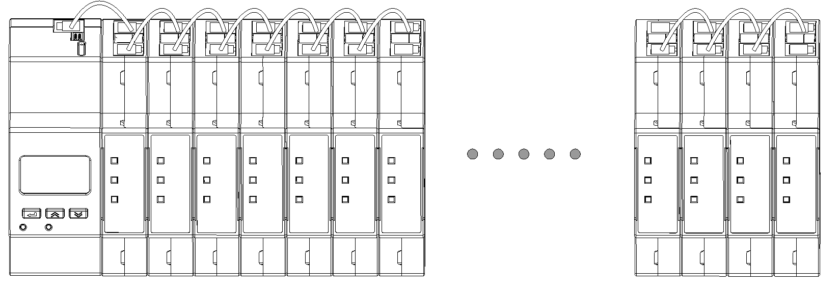
The ADW600 multi circuit power metering module is mainly used to measure three-phase active energy in low-voltage networks, and has the advantages of small size, easy installation, and rich functions. The product adopts a modular design, including voltage module, current module, switch module, temperature measurement and leakage module, etc. The modules are connected by Ethernet cables and can support multi circuit splicing. Suitable for low-voltage side multi circuit metering scenarios, especially for power transformation.
Function
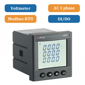
√ Input voltage
3*57.7/100V, 3*220/380V, 3*100V, 3*380V
√ Inputr current
5A, 100A, 400A, 600A
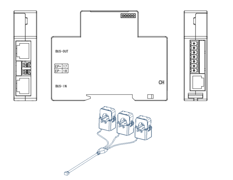
Figure 4 ADW600 -U wiring diagram
ADW600 -U needs to be connected to the load voltage signal. Refer to the wiring diagram below. Terminals 11-14 are connected to the UA, UB, UC, and UN voltage signals respectively. If the three-phase three-wire connection method is used, terminals 11-13 are connected to the UA, UB, and UC voltage signals, and then UB is short-circuited into the UN terminal.
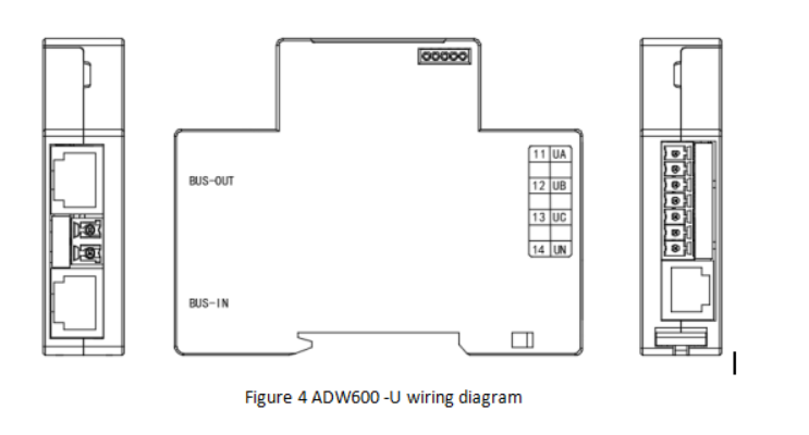
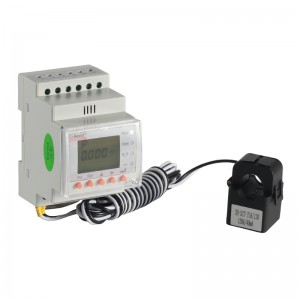
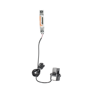
Figure 5 ADW600 -I wiring diagram
ADW600 -I needs to be connected to the load current signal. Refer to the wiring diagram below. The standardtransformer is an RJ12 interface that can be inserted into the meter terminal. The three transformers can be clippedonto the load cables according to the indicated directions
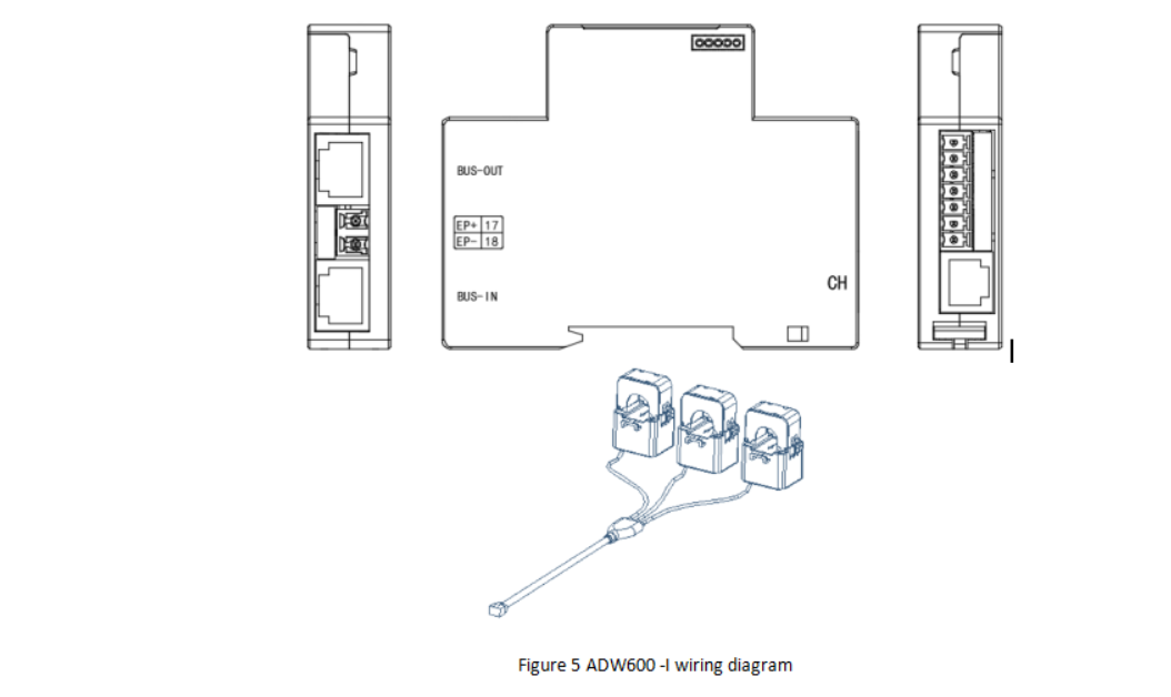
Figure 6 ADW600 -K wiring diagram
ADW600 K is connected to the switch input or output signal line as needed. Note that the COM port is the commonend. Refer to the wiring diagram below.
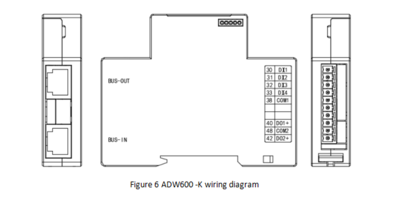
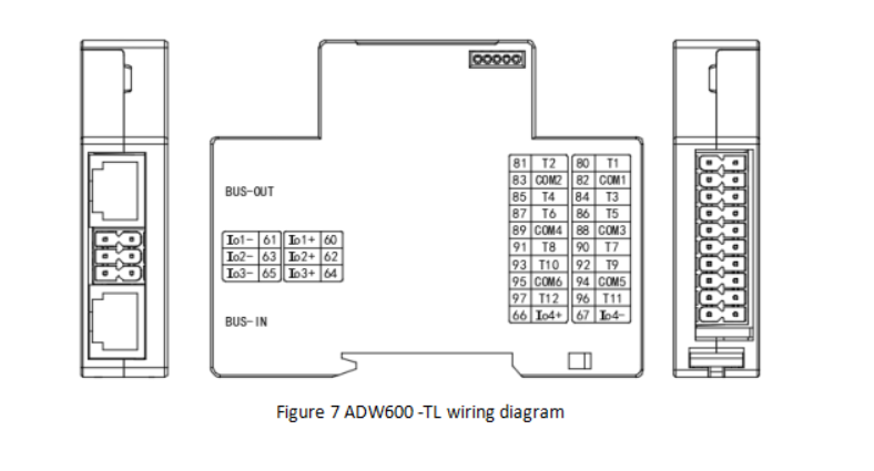
Figure 7 ADW600 -TL wiring diagram
ADW600 -TL is connected to the temperature measurement signal line or the residual current transformer signal line as needed. Note that the COM port is the common end of the adjacent measurement circuits. The specific wiring diagram is as follows.
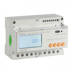
ADW600 Renderings
Wiring
1.Technical parameter
| Item | Performance Parameters | |||
| Model Series | ADW600-U | |||
| Rated voltage | 3×57.7/100V,3×220/380V,3×100V, 3×380V | |||
| Accuracy class | 0.5% | |||
| Frequency | 45-65Hz | |||
| Power consumption | <0.5VA | |||
| Item | Performance Parameters | |||
| Model Series | ADW600-I | |||
| Input current | D10:0.03-0.15(6)A,D16:0.8-2(100)A,D24:3.2-8(400)A,D36:4.8-12(600)A | |||
| Accuracy class | 0.5% | |||
| Pulse width | 80±20ms | |||
| Pulse constant | D10:6400imp/kWh,D16:400imp/kWhD24:100imp/kWh,D36:60imp/kWh | |||
| Power consumption | <0.5VA | |||
| Item | Performance Parameters | |||
| Model Series | ADW600-K | ADW600-TL | ||
| Switching output | 4 DI, with build-in 12VDC power supply | / | ||
| Switching input | 2 DO, Max allowed voltage: AC230V/DC30V, 3A | / | ||
| Temperature measurement | / | 12 temperature measurement channels with 12 NTC, accuracy ±2 ℃ | ||
| Residual current measurement | / | 4 measuring channels, maximum input 1mA, accuracy 1% | ||
2.Environmental condition
| Operating temperature | -25℃~55℃ | ||
| Storage temperature | -40℃~+70℃ | ||
| Relative humidity | ≤95℅ (without condensation) | ||
| Altitude | ≤2000m |