

A monitoring proposal for a Selangor factory whose PCC power factor falls on reduced-production Saturdays.
Project background
A factory may run fewer production lines on Saturday while its rooftop PV continues generating. This Selangor application proposal considers that reduced-load condition, with compressors still operating. The project would first record the factory’s grid exchange, then assess whether ANSVG ↗ compensation is appropriate for the actual reactive-power demand and the existing electrical installation.

The gap in the existing information
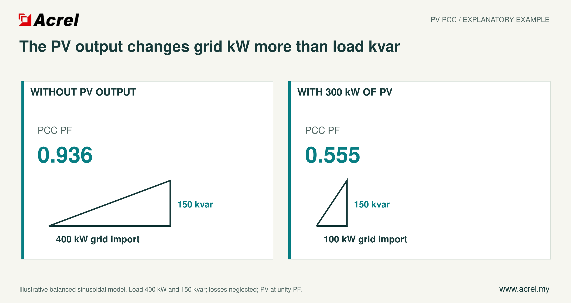
A normal inverter power-factor reading does not explain a poor reading at the factory PCC. PV may reduce imported active power while motors continue drawing reactive power. Without a record covering both production days and reduced-load periods, the team lacks a reliable basis for choosing compensation capacity or deciding how it should work with an existing capacitor bank.
Background note: why a PV installation can lower the power factor at the PCC ↗
Acrel monitoring before equipment selection
Place the monitoring point where it covers the combined effect of the loads and PV. A suitably configured ADW300A ↗ provides active-power, reactive-power and power-factor records to Acrel IoT EMS ↗ through the selected communication path. Check CT orientation and import/export conventions so that the record describes the actual direction of grid exchange.
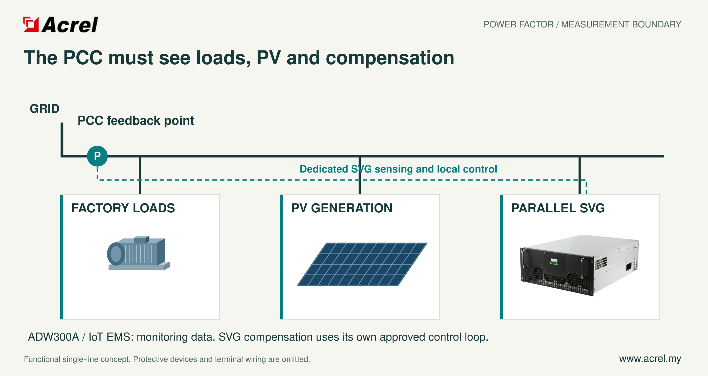
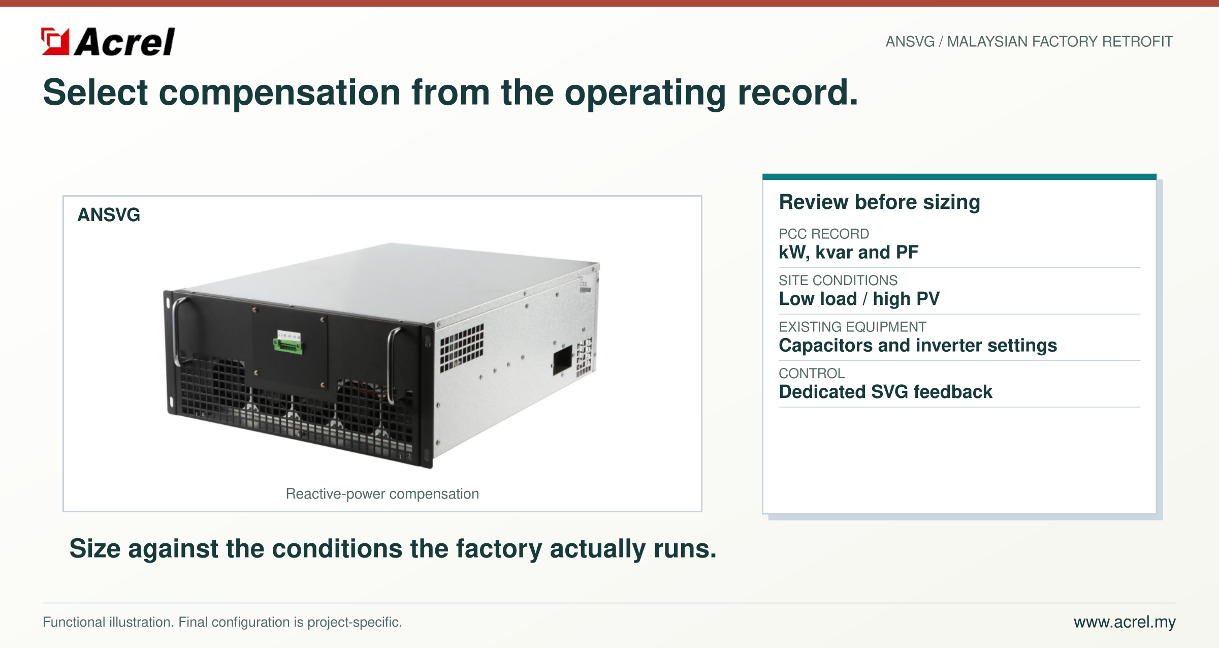
Use representative operating records to assess ANSVG ↗ capacity and its coordination with existing compensation and inverter settings. ANSVG ↗ connects in parallel and uses its own dedicated sensing and local control. The feedback boundary must include the loads, PV and compensation branch. The monitoring meter and cloud platform support review; they are not the compensation device’s fast control loop.
Expected benefits for the factory
The proposed sequence gives the owner a basis for discussing compensation under the conditions that cause concern, including quiet Saturdays. Correctly selected and commissioned compensation can reduce reactive exchange at the agreed boundary. Recording the same operating conditions before and after installation allows the team to check that result instead of relying on a single improved PF display.
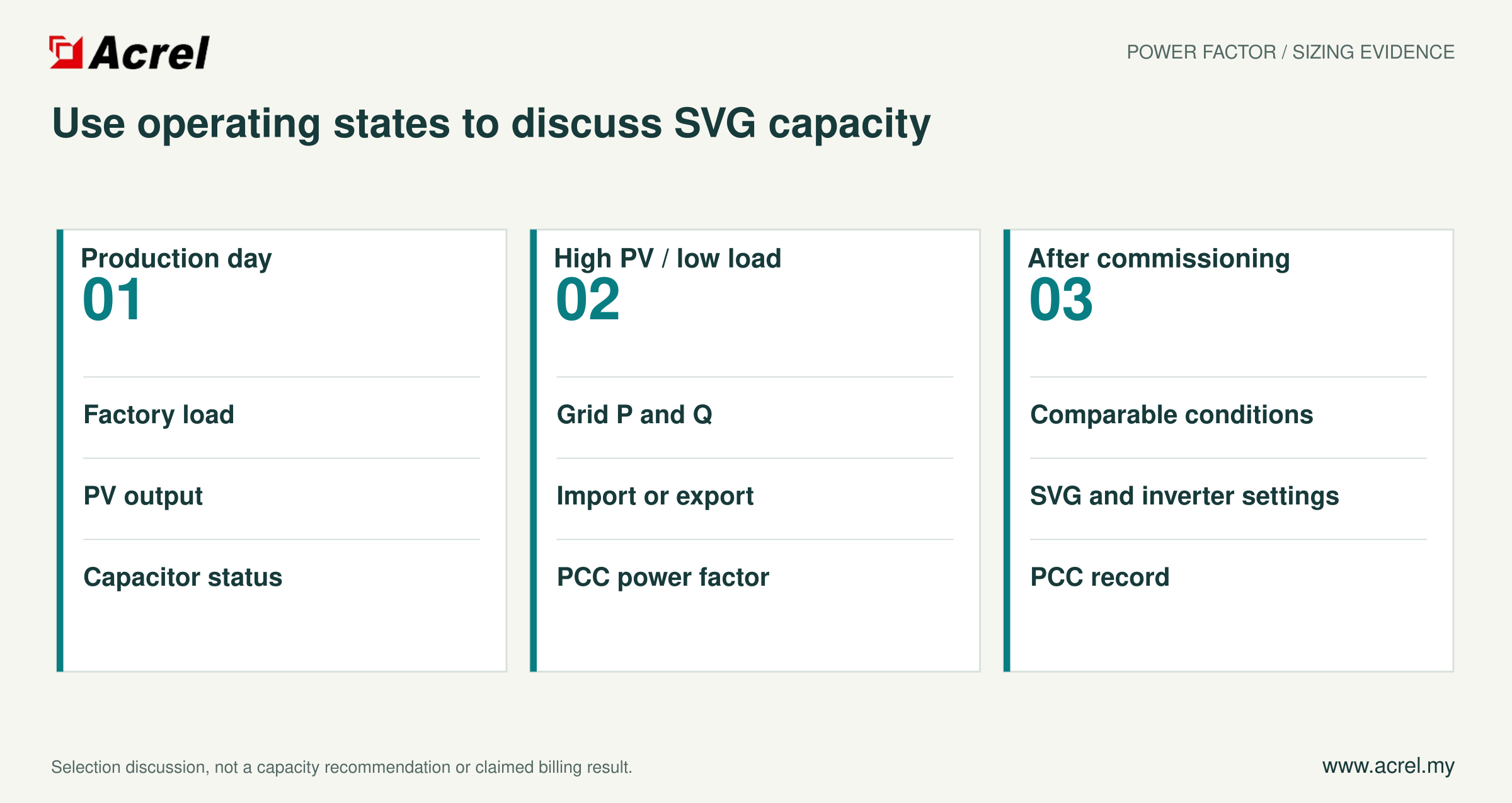
Share the single-line diagram, existing capacitor-bank details and a representative P/Q/PF record with Acrel ↗ to begin the sizing review.
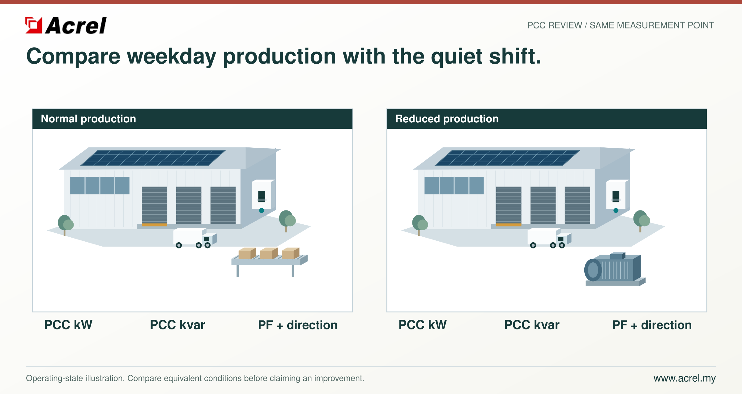
Bring a representative P/Q/PF record from a high-PV, reduced-load day and discuss which conditions the compensation should be sized for.
Post time: Sep-18-2026


