
AWT100-LoRa Wireless Communication Terminal
Overview
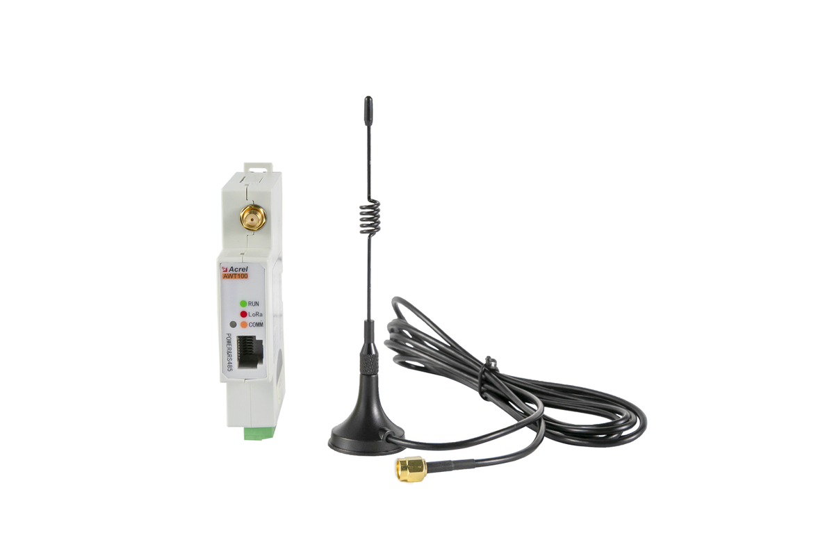
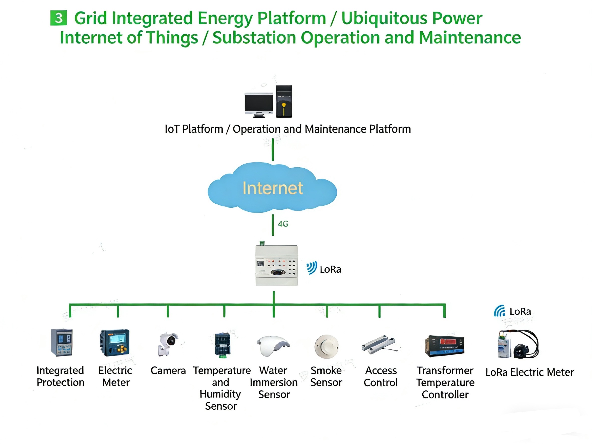
AWT100-LoRa is a compact wireless communication terminal developed by Acrel for extending RS485 communication over a LoRa wireless link. It collects data from power meters, RTUs, PLCs and other field devices through one RS485 interface and sends the data to another AWT100-LoRa terminal installed at the host side. The host terminal connects to a local controller, communication gateway or monitoring computer. This architecture reduces communication cabling in distributed metering, industrial monitoring and retrofit projects.
- · One RS485 interface for downstream Modbus RTU device acquisition.
- · LoRa wireless uplink with a 460–510 MHz operating frequency.
- · LoRa transmission rate of 62.5 kbps.
- · Supports up to 30 downstream Modbus RTU devices.
- · Transparent transmission and relay operating modes.
- · Up to eight device templates, 640 points per template and 3,000 parameters in total.
- · Selectable serial rates: 4800, 9600, 19200 and 38400 bps.
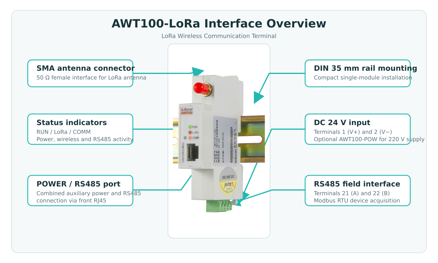
- · 50 Ω SMA female connector for an external LoRa antenna.
- · DC 24 V power input; optional AWT100-POW for an AC/DC 220 V supply.
- · Compact 35 mm DIN-rail installation with a built-in watchdog.
Characters
- · Provides cable-free RS485 extension between a remote field-device group and the host system.
- · A host-side and remote-terminal topology supports point-to-point or relay-style LoRa communication.
- · RUN, LoRa and COMM indicators show operating, wireless and RS485 communication status.
- · Low power consumption is suitable for compact control cabinets and distributed installations.
- · Modbus RTU data can be collected through configurable device templates or transparent transmission.
- · DIN-rail housing and removable terminals simplify installation and maintenance.
- · A built-in watchdog improves continuous operation in unattended sites.
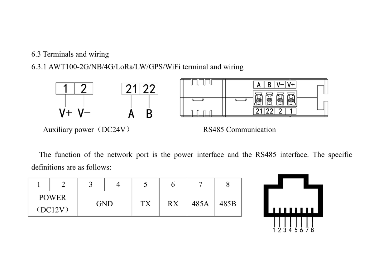
Wiring diagram
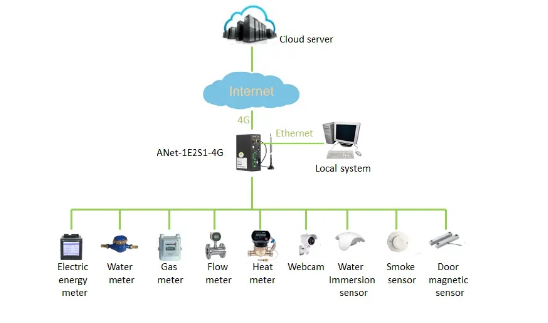
Networking plan

| Parameter | AWT100-LoRa / LoRaHW |
|---|---|
| Downlink Communication | RS485 |
| Uplink Communication | LoRa |
| Serial Port | 1 × RS485 |
| Protocol | Modbus RTU / Transparent Transmission |
| Overseas Frequency | 860–935 MHz (AWT100-LoRaHW) |
| LoRa Spreading Factor | SF7 / SF8 / SF9 / SF10 |
| Signal Bandwidth | 125 kHz / 250 kHz |
| Baud Rate | 4800 / 9600 / 19200 / 38400 bps |
| Default Baud Rate | 9600 bps |
| Operating Voltage | DC 12–24 V |
| Optional Power Supply | AC 220 V with AWT100-POW |
| Antenna Interface | 50 Ω / SMA |
| Installation | DIN 35 mm Rail |
| Downstream Devices | Up to 30 Modbus RTU devices |


Write your message here and send it to us