

The PV system is doing its job. Daytime grid consumption is down and the inverter output looks normal. Then someone checks the main incomer and finds that the power factor is worse than it was before the solar installation.
That result can look contradictory, but it is not unusual at commercial and industrial sites. The PV system may not have created a new reactive load. In many cases, it has simply changed what the utility side sees at the point of common coupling (PCC).
Why can power factor fall after solar PV?
Power factor is the relationship between active power (kW), which performs useful work, and apparent power (kVA). Reactive power (kvar) is still needed by equipment such as motors and transformers. When a PV system supplies part of the site’s active power, the kW imported from the grid can fall sharply while the kvar demand changes very little. The grid-side power factor then falls.
A simple example makes the point. Before PV, a site drawing 800 kW and 250 kvar has a power factor of about 0.95. If solar reduces the grid import to 300 kW while the reactive demand remains near 250 kvar, the grid-side power factor falls to about 0.77. The numbers are only illustrative, but the mechanism is common.
Three checks to make before changing the compensation system
1 The kW/kvar relationship changed
Compare the PCC data during high solar output, low solar output and after sunset. If grid-side kW drops during the day but kvar stays broadly similar, the lower power factor is mainly a ratio problem. This is the first pattern to confirm.
2 The existing capacitor bank no longer matches the load
A capacitor bank selected before the PV installation may use fixed or relatively large switching steps. Once the grid-side load becomes smaller and changes more quickly, the bank can be too slow, under-compensate or over-compensate. Adding more capacitance without checking the operating data can make the result less stable.
3 The PCC or CT arrangement is wrong
The measurement point matters. A current transformer installed on the wrong side of the PV connection, with an incorrect direction, phase assignment or ratio, can give the controller an incomplete picture of the site. Before replacing hardware, review the single-line diagram and confirm exactly what each CT is measuring.
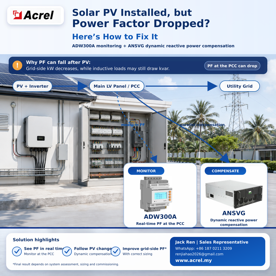
A practical solution: measure first, then compensate
For this application, ADW300A and ANSVG perform two different jobs. ADW300A is used to see what is happening at the PCC. ANSVG is used to correct the reactive-power condition. The ADW300A does not directly control the ANSVG.
ADW300A: establish the actual operating pattern
Install the ADW300A at the main LV incomer or the agreed PCC, with the CTs located and oriented to capture the total exchange between the site and the utility. It can monitor voltage, current, frequency, active power, reactive power, apparent power and power factor, together with forward and reverse energy. Depending on the selected communication option, the records can also be forwarded for trend review.
The useful question is not only ‘What is the power factor now?’ It is ‘What happens to kW, kvar and power factor when PV output rises, a large motor starts, a production line stops, or the existing capacitor bank changes step?’ A short trend record is far more useful than a single screenshot.
ANSVG: follow a fast-changing reactive-power demand
After the load profile is understood, the ANSVG can be sized for the measured compensation requirement and connected in parallel at the selected LV bus. Using its own voltage and current feedback, it generates the compensating current required by the system. This makes it better suited to changing conditions than simply adding another fixed capacitor step.
The installation still needs proper engineering. CT position and direction, system voltage, available cabinet space, protection, ventilation, harmonic conditions and the required kvar capacity all need to be checked before equipment selection.
What should be checked separately?
A low power factor reading does not explain every power-quality problem. If the site also has high harmonic distortion, severe three-phase imbalance, frequent capacitor trips or inverter alarms, those conditions should be measured and assessed separately. The final solution may require more than reactive-power compensation alone.
Planning a site review?
Send us the single-line diagram, transformer rating, PV inverter capacity, existing capacitor-bank steps, CT ratios and a short record of kW, kvar and power factor during high and low solar output. From that information, we can help determine whether the next step is a metering correction, a settings change or properly sized dynamic compensation.
|
|
|
Final performance depends on the site assessment, equipment sizing, installation and commissioning.
Post time: Sep-03-2026


